
If you're enjoying these pages, you
might like to visit my my
other website www.usefulcomponents.com,
where there are details of some components for sale, and some
good electronics kits.
LM13700 VCAs are used in a configuration identical to that shown in the Nat Semi data sheet that produces minimal distortion. It is not perfect but then VCAs never are. Two VCAs are used in inverse polarity for each of the X and Y multiplier sections to guarantee zero output for zero control current. This ensures that change of control voltage amplitude will only result in increased gain and not an imbalance in the B format signal. (This could happen if one VCA was used as a four quadrant multiplier) The reversible quadrature oscillator from the frequency shifter project is used to provide the sine-cosine control voltages for automatic rotation of the output signal. An X-Y joystick with circular outer restraint is used to provide manual sine-cosine voltages for manual signal rotation.
Mono source input 1/4 inch jack
unbalanced mono
B format output 5-pin XLR
unbalanced
LOG CV input 1/4 inch jack mono
LOG manual control ordinary
pot
LIN CV input 1/4 inch jack
mono
LIN manual control ordinary
pot
Oscillator LOG/LIN switch
toggle
Oscillator range switch
toggle
Oscillator direction switch toggle
Joystick - oscillator select
Pan-rotate control joystick
Pan-rotate CV input, 1/4
inch jack stereo, shield GND, X control ring, Y control tip, +/-
1V
Soundstage Rotator
As above except...
B format input 5-pin XLR
unbalanced
B format output 5-pin XLR
unbalanced
Indicators
Each section has a 4-LED indicator where the relative brightness of each lamp represents the direction of the panned sound under any of the three control mechanisms.
Operation
In the mono to B-format section a mono line level input from a synth, recorder playback or other source can be fed into the mono input. The rotated B-format signal appears at the B-format output. In the soundstage rotator a B-format surround signal is fed to the B-format input and appears rotated at the B-format output.
Joystick Mode
The rotate mode switch is set to Joystick. The sound can be panned around the extremity of the soundstage by moving the joystick in a circle around the outer extreme of its travel. The sound can be panned from one side of the stage to the other by moving the joystick from side-to-side crossing the centre position. In the exact centre position the sound will appear to be coming equally from all directions. Any other intermediate positions will result in a valid ambisonic B-format signal represented by the joystick position.
Oscillator Rotate Mode
The rotate mode switch is set to oscillator. The ACW-CW switch is set in either position depending on the clockwise/anti-clockwise sense of rotation required. In this mode the sound is continually panned around the soundstage at a frequency set by the oscillator. For conventional operation the oscillator will be set to the LOW position for slow rotation. In the HIGH position the sound will be spun around at audio frequency so that unusual rotation-modulation effects can be created. The oscillator has two modes of control those being LOG or LIN. In the LOG mode the direction is set solely by the ACW-CW switch and the speed is set in a logarithmic sense by the manual LOG control. Alternatively the oscillator can be controlled in this mode by an input voltage which obeys the 1V/octave synth control law. The voltage is fed into the LOG CV input which overrides the manual setting control. This gives the potential to create unusual synth sounds. The fine tune control allows setting for 5V CV = A440.
In the LIN mode the direction of rotation is controlled by both the ACW-CW switch and the LIN control. In the centre position the LIN control gives zero rotation. Provided that the ACW-CW switch is in the CW position, turning the control clockwise will start the sound rotating in the CW direction and turning the control anti-clockwise will start rotation in the ACW direction. Changing the ACW-CW position changes this direction. Control of the frequency on this control is linear in nature. This mode can also be controlled by an input voltage fed into the LIN CV input. A +5V input is equivalent to advancing the manual control fully clockwise and a -5V input fully anti-clockwise.
External Rotate Mode
The voltages normally created by the oscillator or the joystick can be fed from two external sources of +/1V. For correct Ambisonic panning the vector sum of these two voltages should not equal more than 1V.
Soundstage Rotator
This section takes a B-format input and rotates the whole soundstage in any of the ways described for the other section.

The sheet shows the standard 1V/octave exponential converter circuit and the through-zero quadrature voltage controlled oscillator. Both of these circuits are described fully in the frequency shifter project. The low range of the oscillator is lower frequency in this circuit so that slow rotations can be achieved. On low range the oscillator takes some time to start up as the integrators slowly attain their sine-cosine relationship.

Here we have four precision current
sources to drive the OTA current inputs. The upper sources have
a gain adjustment pot which is not strictly necessary. The
matching of the OTAs within one package is sufficient that 1%
fixed resistors here are perfectly adequate. This is shown in
the full B-format panner, sheet ambisonic_panner02-02. One poitn
of note is the use of 1N6263 Schottky diodes in the negative
feedback path to stop those op-amps going into full reverse
saturation when inactive.
One extra transistor on each current source section provides a larger mirrored current to drive four front panel LEDs. The relative brightness of these LEDs shows which quadrants are currently operating and hence can be arranged to show the current pan direction. This is essential for oscillator mode but is also useful for joystick mode. For a mono signal all the LEDs are off.

This sheet shows the VCAs which provide the X-Y multiplication of the mono input signal. The basic VCA configuration is identical to that shown in the Nat Semi data sheet which gives reasonable distortion performance from cheap devices. The current sources based around Ux and Qx give 400uA into the upper amplifier for +1V and 400uA into the lower amplifier for -1V input to the linear control voltage input. The choice of this architecture, using two OTAs per package to implement the two four quadrant modulators for X and Y is deliberate. It is possible to perform the same function with just one OTA running at a mid current value for zero output, with current values above and below giving +ve and -ve outputs. This has disadvantages though. The zero point depends on the transconductance of the OTA which is temperature sensitive, the OTA provides a noise and distortion contribution over all of the operating range, and the input control voltage amplitude has to be carefully controlled and symmetrical so that the current never hits zero. In this method the OTAs contribute no noise or distortion for mono "W only" signals as they are both off. The zero 'mono' point depends only on the op-amp offsets in the current sources. The X-Y control input voltages can never saturate the current sources unless they are excessively miscalibrated.

This sheet has the auxilliary
circuits common to all sections. Standard regulators provide
regulated +/-5V rails and two op-amps create +/-1V rails to
power the joystick tracks. U11 sums the current outputs from the
OTAs and a gain trim allows the overall gain through the system
to be set to unity.
Four, six-diode limiters have been added here to limit the
possible excursions of the X and Y control voltages to about
+/-1.5V. This is only needed for the X-Y voltages fed from the
external input socket, but all the X-Y signals are fed through
them anyway due to the wiring method chosen previously. It can
be useful to use a pitch CV to control the X-Y panning, and as
these are naturally about 5 Volts in my system, it is all too
easy to feed in control voltages that risk damaging the OTAs.
The signals after the diode limiters are buffered to ensure that
the different input impedances of the upper and lower current
source circuits do not produce different current gains in each
section.
PDF ambisonic_panner_wd01-01.sch

This wiring diagram shows the link
from the circuit board to the front panel equipment. The
joystick is a Farnell part FC 000-000 (TBA). This part must be
modified slightly for correct ambisonic operation. In its
original form the ends of the track are reached before the stick
actually reaches fully left or right, front or back. This is
deliberate on the part of the manufacturer so that the ends of
both tracks are still reached when the joystick is in any of the
fully diagonal directions, despite the circular physical limit.
In unmodified form, this joystick would give Quadraphonic style
panning, with the magnitude of the vector sum of the X and Y
control voltages exceeding 1V in the diagonal positions (if
|X|=1 and |Y|=1 at the same time, then |r| would = 1.41)
The easiest way to prevent this is to wrap just enough
heatshrink tube, fish tank air tube, or some other material
around the stick where it normally meets the circular physical
limit. The trick is to get this material onto the stick evenly
without resorting to sawing the joystick's knob off. There is
another way which works well by chance in this implementation.
If the front panel joystick hole is 13mm the same thing is
achieved, though the accuracy depends on the ability of the
machinist who is drilling the front panel.
It would be perfectly possible to feed the joystick tracks with
actual +/- XY audio signal and avoid the use of VCAs entirely
for the manual panning. I decided against that, fearing
excessive noise from wiper movement in what is quite a cheap pot
with a small track arc. For static panning purposes though, this
might be entirely acceptable and much simpler.


Here we have a total of eight OTAs in four packages. Each requires its own offset adjustment which is tuned for zero dc output offset first and then by ear for minimum control voltage feedthrough. Each package of two amps has a gain trim which sets the overall gain through the system. Matching between the amplifiers in each package is sufficient to allow one trim per package.

U11 sums the current outputs from the OTAs and buffers the W and Z signals to the output unchanged.

This is the wiring diagram for the
soundstage rotator section.
Insides of the Ambisonic Rotate Unit,Top View.

Inside the Unit, Front View.

Here is an example soundfile where the theme tune from "Super Chicken" is played on a midi controlled analogue synth programmed in cubase and controlled via Oakley Sound mididacs. There are three parts being played and mixed down live with no multi-tracking as such. Part one is the bass being played on the hammond organ emulator. This is panned dead centre and as such will appear to come from all speakers equally. Part two is a popcorn voice doing the melody running through the panner running in auto mode rotating clockwise slowly. Part three is a cheesey filtered sawtooth doing super-chicken's clucks which I manipulated manually using the A+D pan-rotate. The B format was UHJ encoded in the A+D encoder rather than processed offline digitally (for now). The result was mp3ed using lame with variable bit rate, which is what you have here.
Super Chicken Theme In UHJ Ambisonic Surround Sound
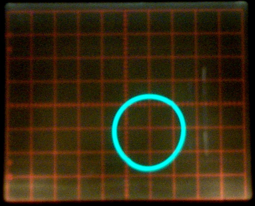
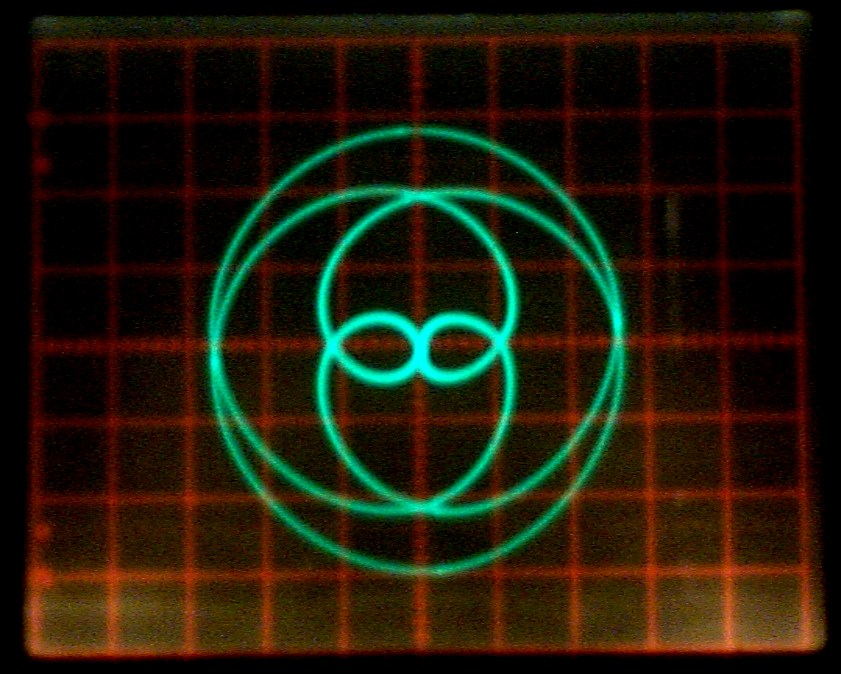
An unexpected bonus of having the
fast oscillator driven rotate mode is the attractive lissajous
curve type plots that you can see if you feed in a sine wave and
adjust the rotate oscillator frequency. The X and Y outputs are
fed to the X and Y oscilloscope inputs. The patterns rotate and
become stationary when the two frequencies are integer
fractionally related. These pictures are with 1kHz on the audio
input and oscillator frequencies as shown. You can see that the
number of petals is related to the ratio, and I have given some
of them somewhat fanciful names. The photographic quality of the
'scope shots varies according to whether they were taken with a
Kodak DC120, or more recently with something less ancient.
Slow Rotation (1/4 second exposure time)


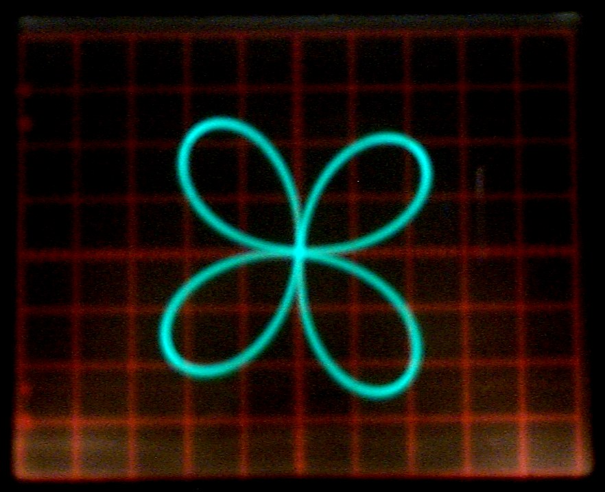

1500Hz Ambisonic Logo
Looking spookily, but not quite exactly like the Ambisonic logo.
Explain to me how this perfectly shows four cardiod patterns
pointing at right angles. I'll be expecting a highly complex and
rigourous mathematical proof, preferably with lots of Laplace
transforms or something in it.
![]()

3000Hz The Dogs


All of the above curves were created
using sine wave inputs. Of course, you can use other
waveforms. Here are some examples. Don't ask me what
those waveforms were for each one, but square waves, triangles,
rectangles, and ramps were involved. It is interesting to think
about creating shapes that look more three dimensional like
spheres and rectangles by using some cunning scheme, and
possibly both panner sections. In fact, I've done a bit of that
in the video linked at the bottom of the page.
Corn Dolly

Evil Eye

Colossus Spiral

Nationwide

London Eye

Sliced Pie

Crystalline Entity

I really hate metalwork, but it has
to be done.


Current Installation

Old Installation

Here you can see the various patterns rotating. I made this video as a visual accompaniment to the Widor Wedding Toccata played on the Mighty Hammondicon. You can find more by looking them up on YouTube. Some of those suggest how, with some additional modulations of amplitude, summing in some further signals, and using the oscilloscope Z intensity input, very cool 3-D looking patterns might be produced.
Henry's main email address:![]()
Recent Edit History
15-DEC-2003: Created
30-JAN-2007: Added diode
limiters to the X-Y control inputs.
14-JAN-2026: html incantations, major updates