Portable Dalek
Voice Modification Ring Modulator Circuit
If you're enjoying these pages and you
have an interest in hobby type electronics or repair jobs, you
might like to visit my my other website www.usefulcomponents.com,
where there are details of some components for sale, and some good
electronics kits.

Introduction
Back in 2011 I started selling
electronics parts online and put together a simple ring modulator
kit like this.
The
Useful Components Ring Modulator Kit
So far so good. Every so often though, customers want a whole
portable unit to do a Dalek voice, and they want do make it
themselves rather than buy one of the plastic Chinese things. So,
back in 2011 I knocked together a breadboard for a bit of
amusement, and just to make sure that my claim of being able to
make a Dalekky sounding voice with that basic ring modulator core
would be possible. We're on Interesting Electronics here rather
than Useful Components, so this design is provided as a circuit
that has been made and tested. It is not available as a kit or
board, and I don't claim that this is the best way to do it. It is
definitely one way to do it though, and I think that it sounds
quite good.
Schematic Circuit Diagram Of The
Portable Dalek Voice Modification Unit

As ever this is displayed here at the width of a postage stamp to
stop Google Search Console complaining that it is "not mobile
friendly," but users of proper computers can click on the image to
enlarge it, or download the pdf at the following link.
PDF
Schematic Circuit Diagram Of Portable Dalek Voice Changer Unit
Schematic Walkthrough of the
Portable Dalek Voice Modification Ring Modulator Circuit
Starting at the microphone input
bottom left, R9 provides the standard bias for a commonplace
condenser microphone element. Q4 is a very standard common emitter
amplifier configuration working near maximum available gain. C7
blocks the DC and the voice signal feeds ring modulator
transformer L1. At the top left there is a classic phase-shift
oscillator, but with an output buffer to ensure sufficient
feedback and some slightly nifty limiting shenanigans involving R4
and R5. This resistor network reduces Q1 base bias and reduces the
gain as the signal output of the stage increases. We don't need a
perfect sine-wave so this simple arrangement is all well and good.
L1, L2, and D1 though D4 are the classic ring modulator core using
diodes and centre tapped transformers configuration. Bottom right,
VR1 onwards is the volume control and simple class B amplifier for
driving the loudspeaker.
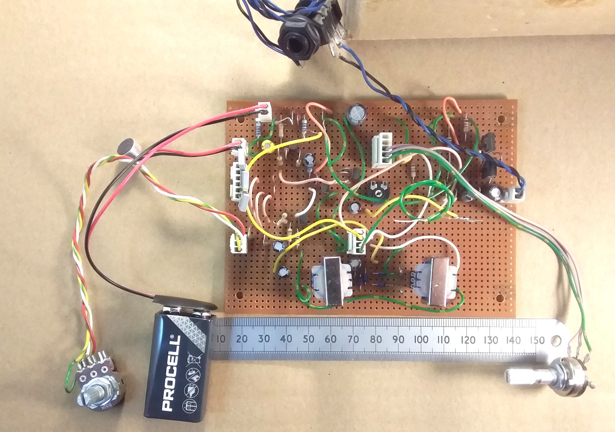
Pictures Of The Portable Dalek
Voice Ring Modulator Prototype
Portable Dalek Voice Modification
Circuit Closer Image

Dalek Voice Converter Transformer Diode Ring Modulator Core

Portable Dalek Voice Impersonator Circuit RIng Mod Core Angle
View

What we're all waiting to know. What does it actually sound like?
Hopefully you can view and hear my top quality video at the link
below.
Portable
Dalek Voice Unit Video Test
If that doesn't work, it's also available on YouTube.
Portable
Dalek Voice Unit Video Test
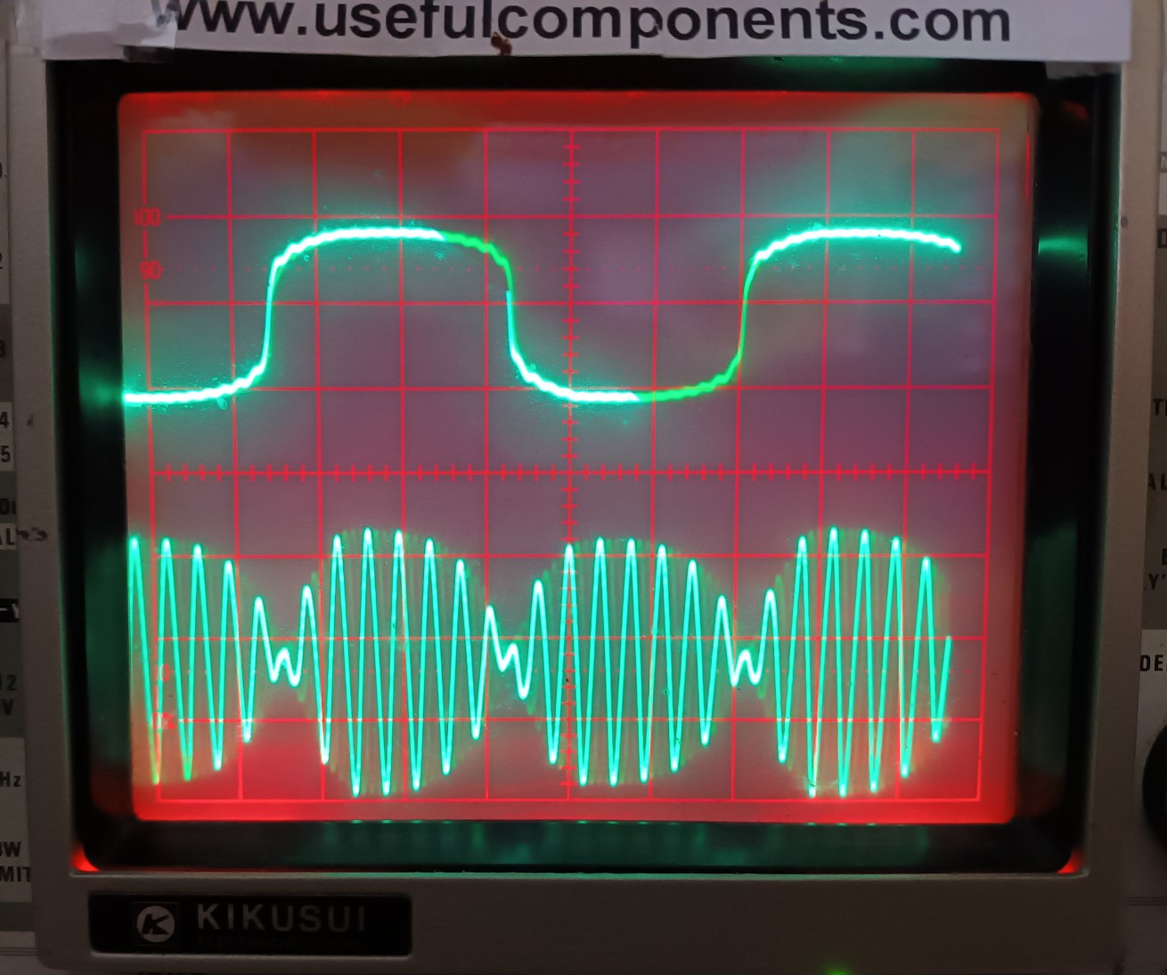
Oscilloscope Picture To Show Double
Sideband Suppressed Carrier Type Modulation
For convenience of the oscilloscope
triggering I've used about 6 kHz audio frequency going into the
microphone input and speeded up the oscillator to about 300 Hz.
You can see the oscillator waveform on the upper trace and the
familiar shape of the suppressed carrier modulated waveform on the
lower trace. Note the phase reversal on the output signal at the
crossover points. This demonstrates that the circuit is working as
intended. I think that red LEDs in the oscilloscope illumination
channels really are the way to go in the age of colour. The
Kikusui graticule was red anyway, so now it shows up properly red.

More Things To Do
Someone has suggested that another
thing that you might want is a relay output that closes a switch
when voice is present. This could activate the two Austin Mini
indicator lights on the head via a battery. As a 1960's BBC
Dalek operator, that would have saved you from having to pull the
light switch cord in time to the actor's voice off-stage, while
simultaneously waggling both the eye stalk, squirty gun, and of
course, the classic sink plunger. Easily done. In true Blue Peter
style, I am told that Davros is working on such an improvement.
But he also says that he's a bit busy at the moment making a
simpler version of this design to supply as a kit which will
hopefully include some lights that will flash along with the voice
output.
Apocryphal Tales
In times long past, the BBC had a
habit of losing the ring modulators. They only had two for a
while, and no-doubt the Radiophonic Workshop were keen to keep
their claws on theirs, and not to have that one nicked as well. At
one audition, the prospective Dalek voice actor said, "Oh, so
what; You want me to do it without the effects unit? No Problem!"
And he did. Perfectly:)
Other Notes
If you were viewing the schematic
published on this page a while back, there was a mistake in it
around R3 and the Q2 biassing. I'd changed this on the original
schematic while building the breadboard, but failed to update the
change to this site. Naughty! Thank-you to the observant viewer
who pointed this out via email. If you want more loudness, you can
use an ancient TBA820M or similar audio output amplifier chip
after the volume control. I've since soldered the LT44
transformers directly into the board. A lightly driven double
diode limiter in the oscillator is better if you want to create a
less distorted sine wave over a wider range of frequencies for
doing more pure and higher oscillator frequency ring mod effects.
Henry's email address:
Navigate
Up
Recent Edit History
03-OCT-2024: schematic correction around R3 and Q2 biassing,
removed rogue "wire"
02-FEB-2026: significant update, scope picture, html incantations


